Although normal maps are widely used they are not commonly understood. The description below is provided as assistance to emerging CG artists to allow them to better use normals to their advantage when lighting the elements of a scene.
What is a Normal?
The term, normal, or better yet, surface normal, is the mathematical name for a vector (an arrow) pointing away from the surface. This surface normal is used in lighting calculations. The orientation of the surface normal when compared to the position of the viewer and the position of the light source will result in the pixels in the image being rendered brighter or darker. Models created by 3D software store a normal with each vertex which is used by the rendering software and referred to as the vertex normal.
What is a Normal Map?
A normal map is a file like a texture map, except that rather than storing colours,
it stores the surface normals that are used when rendering the pixels in the image.
By using the normal from the normal map, rather than the vertex normal, the renderer is effectively fooled into behaving as if there is a lot more detail than what the vertex data actually provides. 
The normal data is stored in an image file using RGB data. However, that RGB data is actually interpreted as XYZ positional information.
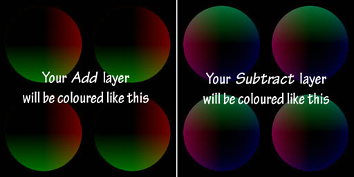
When viewed as an image, normal maps often appear somewhat desaturated, with a bluish cast (look at the images below). This is because while there are large variations in the values of X (red) and Y (green), the Z (blue) value is always pointing directly away from the surface and doesn't vary much.
Most normal maps used in 3D rendering are stored as tangent space values, which means that the normals are always pointing away from the surface (perpendicular to the local tangent), similar to the vertex normal. This type of normal map is also referred to as being in object space. Normal maps can also be stored as world space normals but this is less common and not described here.
Creating Normal Maps
Although you can view a normal map as an image, it is very difficult to paint them by hand. There are many ways to create normal maps including within most modelling programs and by using specialized 3D sculpting software.
Combining Normal Maps
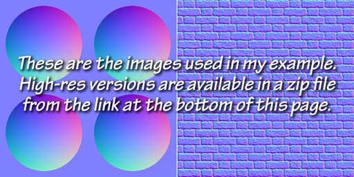
It is often desirable to combine two normal maps to get a richer result. For example: To create a dragon skin look you might want to add a leather-like normal map to skin fold normals you've created using Z-brush or Mudbox.
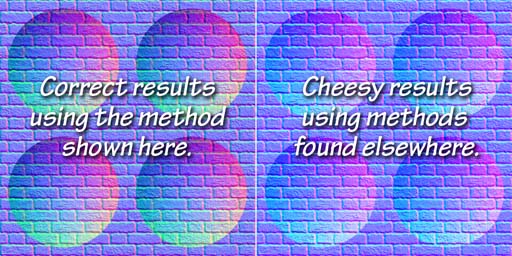
The method for properly combining normal maps to create such a complex looks is not obvious and is often done wrong. Simply blending the two normal map images together gives a result that might appear OK at first glance, but used in a render will produce incorrect results. The fact is that the normals are mathematical vectors (not the colours you see) and to be combined correctly they be added together or subtracted from each other to get a correct result.
To properly combine maps, we need to add the positive values (> 128) together and subtract the negative values (< 128). Fortunately this can be done inside Photoshop using the channel mixer to properly combine each vector.
The following steps in Photoshop will properly combine two normal maps.
Follow these steps carefully!
- Open either of the two normal map images you wish to combine in Photoshop, and copy the layer to create two identical layers. Name one layer Add and the other Subtract.
- Adjust the Levels
-
To the Add layer: In the Levels window, adjust each channel separately, setting the red and green input levels to 128, 1, 255 and the red and green output levels to 128, 255. Set the blue output levels to 0, 0 to mute this channel.
- To the Subtract layer: In the Levels window, adjust each channel separately, setting the red and green input levels to 0, 1, 127 and the red and green output levels to 0, 127. Leave the blue channel as is.
- Use the Channel Mixer to shift the Add and Subtract layer pixel values to either side of the midpoint (128).
- To the Add layer: In the Channel Mixer again operate on each output channel separately. For the red channel, set the source channel values to (+100%, 0%, 0%) for (r, g, b) and the constant to -50%. The green channel is similar, except that the source channel for green is set to +100% with the others at 0%. The blue channel has the source channel for blue set to +100% but the constant is set to 0%.
- To the Subtract layer: Channel mixer values are similar to the Add layer except that the %'s are set to -100% for the source channels and +50% for the constant. For the blue channel, also set the source blue to -100% but set the constant to +100%.
- Set the blend modes:
- For the Add channel, set the blend to Linear Dodge.
- For the Subtract channel, set the blend to Difference.
- Now, import the other normal map image as a layer below the Add and Subtract layers created in the steps above. Flatten the result and save as a TIFF or PNG file.
- TIFF settings: use LZW compression and discard any layers.